DX100 Flight Control
- Main processor:
- Co-processor:
- Remote control signals:
- IMU sets:
Product Description
DX100 Logistics Integrated Flight Controller
Basic Parameters of Flight Control Kit
Product List
• Standard Package Contents
Before using this product, carefully inspect the contents of the product packaging to ensure the following items are included. If any items are missing, please contact our company.


• Optional Equipment List


Hardware Installation Instructions
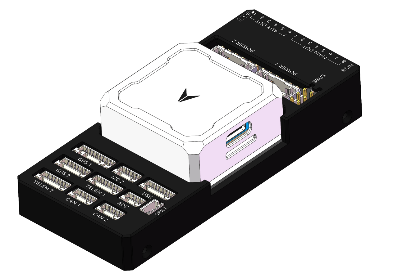
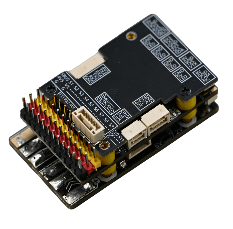
Master Control Installation
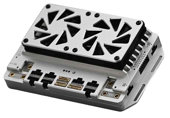
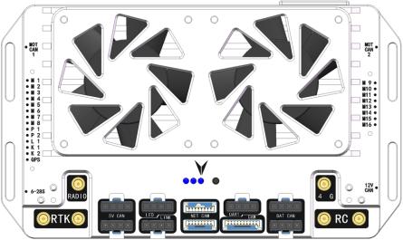
• Flight Control Wiring Diagram
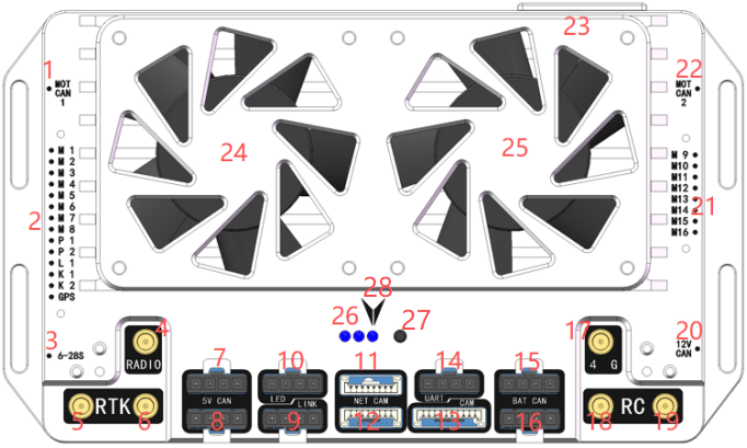
1: Motor CAN signals M1-M8.
2: Outputs motor signals M1-M8; Ports P1, P2, L1, K1, K2 output PWM signals.Connects to GPS.
3: Flight controller power supply voltage: 6-28S.
4: Insert radio antenna.
5: Insert RTK main antenna.
6: Insert RTK auxiliary antenna.
7 and 8: CAN communication, provides 5V power supply; typically connects to CAN GPS, CAN magnetometer.
9: Connects to parameter tuning software, data transmission, and upgrades.
10: Connects to LED lights.
11, 12, and 13: 12V power supply and LAN.
14: Debugging port.
15 and 16: Connect smart battery CAN signals.
17: Insert 4G antenna.
18 and 19: Insert receiver antennas.
20: Connect obstacle avoidance radar, terrain following radar, and weighing module CAN signals.
21: Motor signal outputs M9-M16.
22: Motor CAN signals M9-M16.
23: Insert SIM card to provide network for RTK.
24 and 25: Cooling fans.
26: Left blue-purple light flashing indicates normal frequency synchronization. Center red light steady indicates normal 4G link (light off without SIM card). Right green light steady indicates normal flight controller power supply.
27: Receiver frequency synchronization button.
28: Flight controller installation orientation.
Note: Use 2.54mm thick connectors for the DuPont pins plugged into the flight controller.
• Flight Controller Installation Requirements
1. Must be oriented face-up, not inverted, and kept as parallel as possible to the airframe.
2. For optimal flight performance, mount the flight controller horizontally at the aircraft’s center of gravity.
3. Internal vibration damping is built into the flight controller; secure it using rigid 3M adhesive.
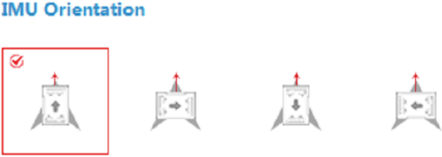
• Flight Controller Installation Orientation Requirements
As shown in the figure, select one of the installation orientations and choose the corresponding configuration in the Parameters Tuning Software under Basic -> Installation -> IMU Orientation. (The red arrow indicates the direction of the aircraft nose.)
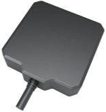
GPS Module Installation
• Orientation Requirements
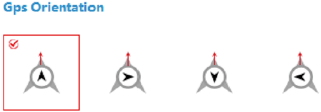
As shown in the figure, select one of the installation orientations and choose the corresponding configuration in the K++ parameter adjustment software under Basic -> Installation -> GPS Orientation. (The red arrow indicates the direction the aircraft nose should face.)
• Installation Location Requirements
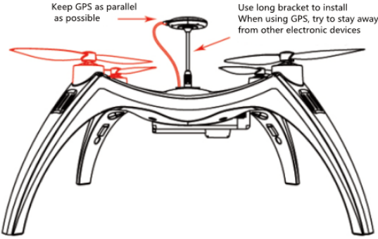
1. Mount the GPS module as high as possible, keeping it away from ESCs, power cables, and motors.
2. Fly in open, unobstructed environments whenever possible.
3. Avoid flying in areas with magnetic interference.
4. Do not place strong magnetic materials near the compass, as this may cause permanent damage.
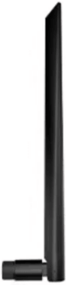
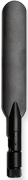
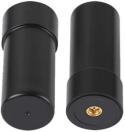
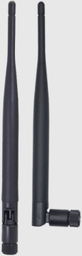
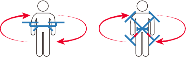
Helical Antenna Installation Method
The minimum distance between the main antenna and the auxiliary antenna is 30 cm. The main antenna and auxiliary antenna must be installed vertically.
• Installation Angle Settings
Configure the installation angle in the computer parameter adjustment software as shown in the figure:
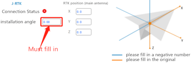
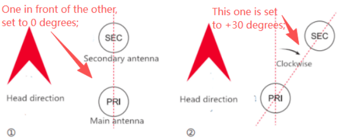
• Installation Angle Calculation Method
The shortest distance between the main antenna and the secondary antenna is 30cm.
The main antenna and the sub antenna must be vertical. If the installation is off, you can set it in the Assistant Software-Advanced-Expansion Module interface.
Rack Type Configuration
The rack types supported by the integrated controller are shown in the figure below:
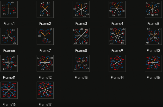
Note:
1. The direction of the yellow arm in the diagram indicates the nose direction.
2. The numbered markings correspond to flight controller input ports M1 through M8.
3. Coaxial multi-rotor configuration: blue denotes upper-layer propellers, red denotes lower-layer propellers.
Flight Test
Remote Control Function Guide
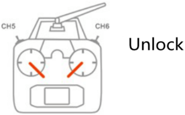
1.Unlocking and Locking
• Unlock
Follow the diagram to unlock. After unlocking, the motor enters idle mode.
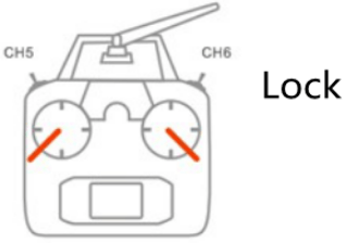
• Locking Mechanism
a. Immediate Locking
In any flight mode, after the motor starts, performing the stick operation shown in the diagram will immediately stop the motor.
Note: In case of an emergency during flight, execute the stick operation shown in the diagram to prevent accidents.
b. Auto-Lock
All flight modes feature automatic landing detection, automatically controlling motor shutdown. When the throttle is pulled to the minimum position during flight, it will not cause the motors to stop.
2. Accelerometer Calibration
The flight controller supports accelerometer calibration via the app or parameter adjustment software. Follow these steps: Place the aircraft horizontally, then tap “Accelerometer Calibration.” Calibration will complete within 3-5 seconds. Note: Do not shake the aircraft during calibration.
3.Magnetic Compass Calibration
The K++ flight controller supports magnetic compass calibration via remote control stick movements. Proceed as follows:
With the flight controller locked, rapidly toggle the 5th channel flight mode switch back and forth to enter dual-plane magnetic compass calibration. A steady yellow LED indicates horizontal calibration. Position the aircraft level with gravity aligned along the axis. Rotate clockwise until the LED turns solid green, then proceed to vertical calibration. With the nose pointing down and gravity aligned along the axis, rotate until the LED alternates between red, green, and yellow flashes, indicating calibration completion.
4. Motor Testing
The motor testing function includes sequential motor testing and rotation direction testing. It primarily verifies the correct installation sequence and rotation direction of motors to prevent accidents caused by incorrect installation.
• Motor Sequence Test
With the system locked, move the left stick ↙ and perform a counterclockwise circular motion with the right stick ↗↖↙↘ (American-style control). This initiates the motor sequence test, causing motors 1 through 8 to idle-start sequentially.
Japanese-style joystick sequence test procedure: 1. Move left stick ↙ and right stick ↘ and hold; 2. Then move left stick ↖, right stick ↙, left stick ↙, right stick ↘. Throughout this sequence, keep the left stick fully left and the right stick fully down. Repeat the four joystick movements from step 2 to trigger the generator sequence test.
Note:
Under normal conditions, executing one stick movement triggers the generator sequence test. If stick positioning is inaccurate, repeat all four movements in step 2 to trigger the test.
• Motor Direction Test
After unlocking, the aircraft’s propellers should run smoothly at low idle speed. Use the transmitter’s four channels to verify whether forward/reverse and left/right steering produce opposite effects. For example: – At idle, pushing the forward stick causes the rear propellers to rotate while the front propellers stop. – Similarly, moving the left stick causes the left propellers to stop while the right propellers rotate.
5.Remote Control Loss Protection
First, correctly configure remote control loss protection in the Parameters Adjustment Software under the Basic -> Remote Control interface. When GPS satellite signals are strong, if the receiver signal is lost, the flight controller will execute loss protection regardless of the aircraft’s current flight mode. If the remote control signal is restored and you wish to regain control of the aircraft, you must toggle the flight mode channel to reacquire control.
Introduction to Flight Mode
1.Attitude Mode
Attitude Mode is suitable for users returning to the control center. During flight, the IMU, GPS, magnetic compass, and barometer all participate in operation. Attitude Mode can automatically switch control methods based on GPS signals. When GPS is unavailable or weak, it uses altitude hold flight; when GPS signals are strong, it enables precise positioning and altitude hold. Attitude Mode does not feature terrain following.
• Working Conditions
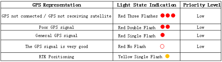
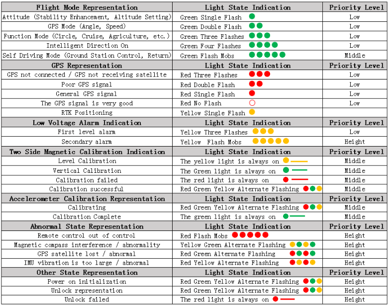
The Attitude Mode requires the GPS module to be operational, necessitating completion of satellite acquisition and attainment of the required positioning accuracy. As shown below, when the LED indicates a GPS status of “GPS Signal Normal”, “GPS Signal Excellent”, or “RTK Positioning”, the device can be unlocked or switched to this mode.
The flight controller can only be unlocked in Attitude Mode; it cannot be unlocked in other modes. After entering Attitude Mode, the green LED will flash once.
• Operation Instructions
After GPS satellite acquisition completes and positioning succeeds, switch the remote control’s 5-channel mode selector to Attitude Mode. After unlocking the stick, motors idle below 50% throttle. Gently push throttle beyond 50% for takeoff. When the throttle stick is released to the 50% position, the aircraft will hover at altitude. When the aircraft is in motion, returning all control sticks to center position will automatically engage brakes and initiate hovering.
Specific stick functions are detailed in the table below:
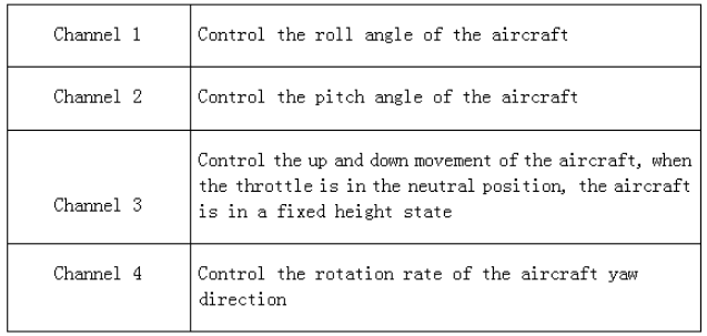
2. Manual Operation Mode
Manual Operation Mode, also known as GPS Mode, utilizes the IMU, GPS, magnetic compass, and barometer during flight. This mode features terrain-following capability.
• Operating Conditions
Operating conditions are identical to Attitude Mode. This mode cannot be unlocked directly. First unlock in Attitude Mode before switching to this mode. Upon entering Manual Operation Mode, the LED green light will flash twice.
• Operation Instructions
After unlocking in Attitude Mode, switch the 5-channel mode selector on the remote controller to the Manual Operation Mode position. When the throttle stick is set to 50%, the aircraft will hover at a fixed altitude and position. If the aircraft is in motion, returning all remote controller sticks to center position will cause the aircraft to automatically brake and hover.
3. Route Operation Mode
Route operation mode enables autonomous flight planning via the mobile app, where users map fields and adjust flight paths before the flight controller executes tasks independently.
• Operating Conditions
After satellite acquisition completes and positioning accuracy meets requirements (LED red light stops flashing or flashes once), click “Execute Task” in the app’s operation interface. Once parameters are set, the flight controller automatically unlocks and takes off. Upon entering route operation mode, the LED green light flashes four times.
4. Auto Return Mode
Auto Return Mode provides safety assurance for long-distance flights and loss-of-control protection.
• Operating Conditions
After satellite acquisition completes and positioning accuracy meets requirements (LED red light stops flashing or flashes once), the flight controller automatically records the current position as the return point each time the user unlocks. Upon entering Auto Return Mode, the LED green light flashes rapidly.
• Operation Instructions
Auto Return mode can be triggered via the joystick or through loss-of-control protection. When the CH6 mode switch on the remote control is set to the one-touch return position, or when the flight controller enters loss-of-control protection, if the aircraft is more than 2 meters away from the return point, it will automatically ascend to the preset altitude (if the current altitude exceeds the set return altitude, it will return at the current altitude). Upon reaching the return point, the aircraft will first hover for approximately 3 seconds before slowly descending. During this phase, the flight state can be controlled via the remote control sticks (though the throttle stick will not function), allowing the aircraft to seek a more suitable landing spot. The aircraft will automatically lock once it has fully landed. If the aircraft is within 2 meters of the return point, it will land in place and automatically lock.
Important Notes:
Automatic return requires the return point to be pre-recorded. To use this feature, ensure GPS satellite acquisition is complete before unlocking. Refer to the appendix for LED indicator meanings.
When the aircraft is near people, avoid activating automatic return to prevent accidents.
Appendix 1 LED Three-Color Indicator Status
DroneSafer Flight Controller Series
Compare flight controllers by interfaces, sensors, and supported GPS/RC systems.