Flight Control
- Main processor:
- Co-processor:
- Remote control signals:
- IMU sets:
Product Description
Flight Control
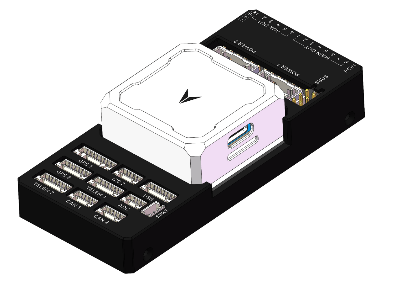
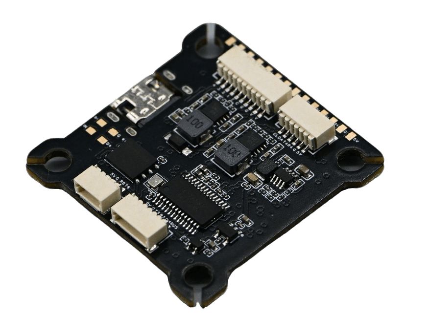
Flight Control Front View Preview Diagram

The 5V pads on the flight controller are outputs from the voltage regulator chip. They can only output voltage when the battery is connected; connecting only the USB cable to the flight controller’s 5V pads will not produce any output.

This is the connection for the analog camera pad:
CAM: Camera, connect to the signal output of the analog camera.
5V: The 5V voltage output from the flight controller, used to power the analog camera or external sensors.
G: GND, connect to the GND of the analog camera or external sensors.
CC: No connection required (NC).

This is the connection for the analog video transmitter (VTX) pad:
VTX: Video Transmitter, connect to the signal input of the analog video transmitter.
The power pad should be selected based on the input voltage range of the analog VTX. If the minimum input voltage of the VTX is greater than 5V, please use the 9V pad to power it.
5V: The 5V voltage output from the flight controller, used to power the analog VTX or external sensors.
9V: The 9V voltage output from the flight controller, used to power the analog VTX or external sensors.
G: GND, connect to the GND of the analog VTX or external sensors.
To prevent the video transmitter from overheating and burning out during power-on debugging or prolonged stationary use on the ground, the flight controller provides a controllable 9V power switch function. This allows the VTX to be turned on/off via the remote controller, improving device safety.
Setup steps (using Betaflight Configurator 10.10.0 as an example):
1.Open the Betaflight Configurator and navigate to the “Modes” tab.
2.Scroll down, locate the “9V BEC OFF” mode entry, and click “Add Range”.

3.Click the “Auto” button and toggle any switch channel on the remote controller. The system will automatically recognize that channel.
4.Drag the range slider to set the switch position corresponding to the VTX power-off state. (It is recommended to set the default state to OFF.)
5.Click “Save” to complete the setup.

Worried about accidental activation during flight? Alternative physical always-on solution: If you are concerned about accidentally toggling the remote control switch during flight and cutting power to the VTX, you can also directly short the 9V pads on the flight control board to keep the VTX power permanently on. In this case, the remote controller will not be able to control the 9V power supply, but it maximizes flight stability.


If you are using a receiver that outputs SBUS signal, please short the SBUS pad. The SBUS receiving pad uses the RX of UART6. After shorting the SBUS pad, R6 will no longer be available for other signal inputs.
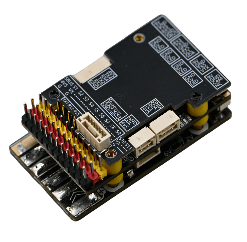
Flight Control Back View Preview Diagram


This is the 10-pin interface for connecting ESCs, and its letters are abbreviations:
V: VCC, connect to the positive terminal of the battery or the VCC on the ESC.
G: GND, connect to the negative terminal of the battery or the GND on the ESC.
C: Current, connect to the Current interface of the ESC or leave unconnected.
T: Telemetry, connect to the telemetry interface of the ESC or leave unconnected.
1~4: Connect to signal wires 1 to 4 of the ESCs.

This is the 6-pin interface for connecting the GPS. Its labels are abbreviations:
5V: The 5V voltage output from the flight controller, used to power the GPS or external sensors.
G: GND, connect to the GND of the GPS or external sensors.
CL: SCL, connect to the SCL of the GPS or external sensors.
DA: SDA, connect to the SDA of the GPS or external sensors.
T4: The TX pin of the flight controller’s UART4, connect to the RX on the GPS.
R4: The RX pin of the flight controller’s UART4, connect to the TX on the GPS.

This is the 4-pin interface for connecting the receiver. Its labels are abbreviations:
V: The 5V voltage output from the flight controller, used to power the receiver or external sensors.
G: GND, connect to the GND of the receiver or external sensors.
T6: The TX pin of the flight controller’s UART6, connect to the RX on the receiver.
R6: The RX pin of the flight controller’s UART6, connect to the TX on the receiver.
The following diagram is a reference example.


This is the 6-pin interface for connecting the digital video transmitter (VTX). You may leave it unconnected if you are not using a digital VTX.
9V: The 9V voltage output from the flight controller, used to power the digital VTX or external sensors.
G: GND, connect to the GND of the digital VTX or external sensors.
T3: The TX pin of the flight controller’s UART3, connect to the RX on the digital VTX.
R3: The RX pin of the flight controller’s UART3, connect to the TX on the digital VTX.
Specifications
Product Specifications
Product Description
Betaflight Usage Guide
If your flight controller has no firmware installed or requires a firmware update, please visit: https://app.betaflight.com/#
Press and hold the button on the board, then connect the board via USB. The webpage will recognize the board and enter updae mod.

Open the firmware flashing option.

Select the firmware.

Click “Load Firmware” and wait for the firmware to load completely. Then click “Flash Firmware”.

After successful flashing, connect the board. For first-time use, calibration is required.

Next, enable the corresponding serial port switch according to the receiver connection.

You can then configure the desired flight modes.

Finally, remove the propellers from the drone and verify the motor sequence.

If the sequence is incorrect, you can reset it.

DroneSafer Flight Controller Series
Compare flight controllers by interfaces, sensors, and supported GPS/RC systems.