F405 Wing Flight Control
- Main processor:
- Co-processor:
- Remote control signals:
- IMU sets:
Product Description
F405 Wing Flight Control


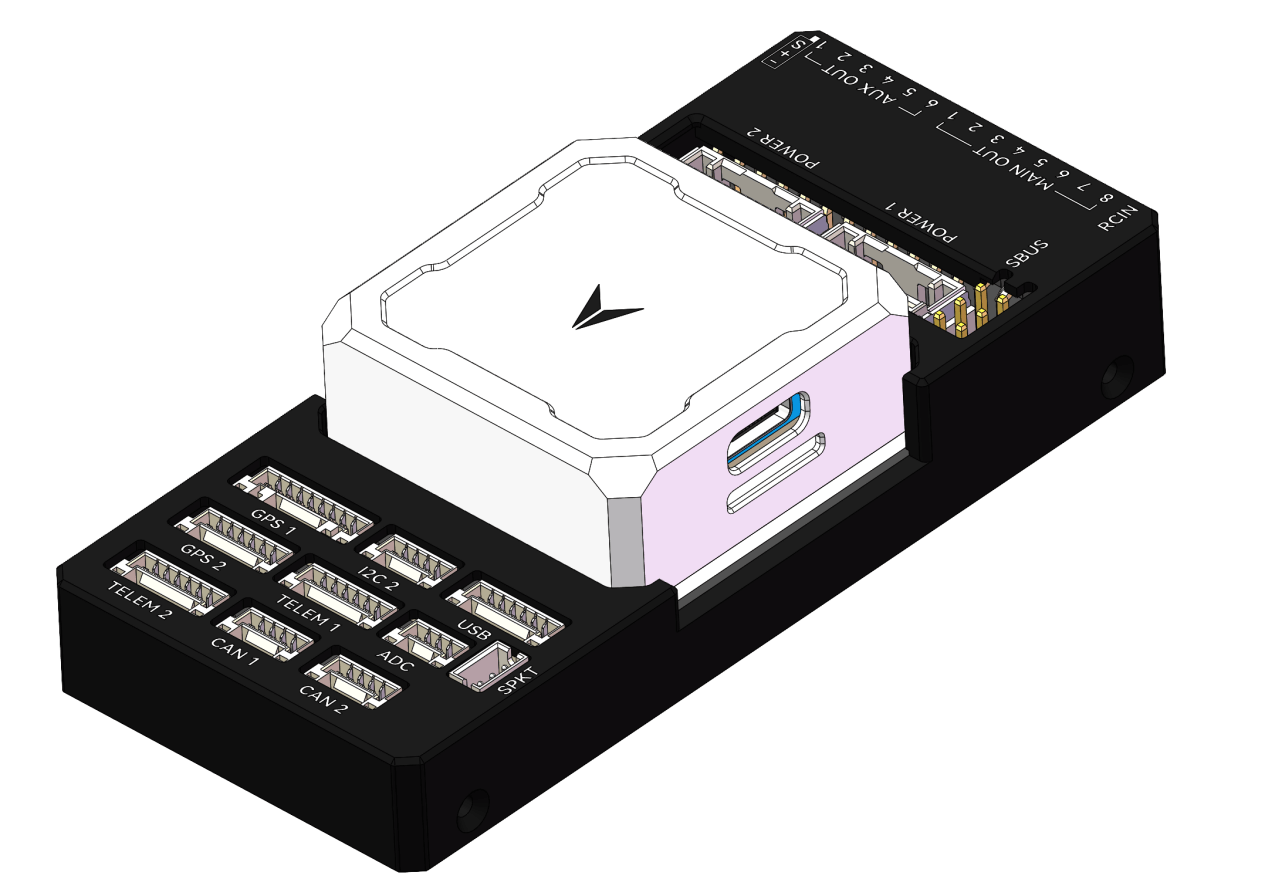
Main Body Installation
Install the flight controller as close as possible to the center of gravity of the aircraft. Ensure that the arrow direction on the autopilot is consistent with the forward direction of the vehicle.

• Installing the Memory Card
The flight controller can use a microSD Card to save logs. Insert the memory card into the card slot on the left side of the flight controller. It is recommended to use a microSD Card with a transmission speed of Class 4 or higher. (The SD card is pre-installed at the factory)
Note: If no memory card is inserted, the buzzer will emit an error prompt tone of one high and two low beeps.
• Power Connection
The flight controller supports two types of power input, namely: power pad input and USB input.
• Power System Connection
Connect the signal wires from the ESC or servo of the power system to the PWM signal output interface according to the wiring definition of your aircraft model.
In most cases, ESC responsiveness issues are caused by incorrect wiring. Always connect both the signal and ground wires. Check your ESC type to determine how to connect the +5 V cable. The signal and signal ground must be connected for the ESC to function. Ensure that the pin signals and GND are correctly matched.
• About ESC Connection
According to the motor number, connect the 3-Pin signal wire of the ESC to the PWM OUT interface in the order defined by the aircraft model. The following figure shows the motor numbers for each frame type. The numbers indicate which output pin of the flight controller is connected to which ESC. The propeller direction is shown in green (clockwise) or blue (counterclockwise). More frames can be viewed on ArduPilot.


• About Servo Connection
The connection channels of the servos can be freely assigned in the “Initial Setup – Required Hardware – Servo Output” of Mission Planner.
• Sensor Connection
The flight controller supports the connection of various sensors, and the connection methods are I2C, and ADC respectively.
For specific parameter settings, please refer to the instructions of the sensor you purchased first. See the list of sensors supported by ArduPilot.
• GPS Connection
For the installation of the GPS module, a good working environment should be provided for it. The GPS needs to have a sufficiently clear view of the sky in the structure of the UAV, and should be as far away as possible from radio transmission equipment, motors and ESCs. GPS with an onboard compass requires regular installation orientation. During installation, note that the direction should point to the nose direction, and the installation needs to be firm and reliable. The GPS signal is better in a wide and clear sky view. Stable GPS positioning effect is very important for automatic tasks and flight safety.
Some high-power wireless devices may interfere with the compass and GPS satellite search. Try to place high-power devices away from the GPS.
GPS Working Modes
• Single GPS Connection
If a GPS with an IIC interface is used, connect the 8-pin connector to the GPS1 of the flight controller. Usually, no parameter setting is required in I2C mode.
Generally, the GPS has a built-in external compass, which is recognized as Compass 1 by default, and it needs to be calibrated in the settings.
• R/C Wireless System Connection
The flight controller supports the following receiver with various signal types. According to the signal type of the receiver, connect it to the corresponding interface of the carrier board.
• Futaba S.bus Signal Receiver
The Futaba S.Bus receiver can be directly connected to the SBUS interface on the rear side of the carrier board.
• Spektrum DSM/DSM2/DSM-X Satellite Receiver
It can be connected to any serial port of the flight controller, and then set the corresponding serial port as RCIN and set the baud rate.
• IBUS/CRSF and Other Receivers Using Serial Port Communication Directly (such as ELRS)
It can be connected to any serial port of the flight controller, and then set the corresponding serial port as RCIN and set the baud rate.
• Wireless Data Transmission Connection
The main function of wireless data transmission is to realize two-way communication between the autopilot and the ground station, so as to view the information of the autopilot and control the autopilot on the ground station.
Data transmission configuration requirements: support MAVLink protocol or transparent transmission, TTL serial port signal interface.
After configuring the data transmission, you need to first confirm whether the wire sequence matches the definition of the TELEM1 interface of the autopilot. If not, please change the wire sequence. After confirming the wire sequence is correct, connect the data transmission interface to either TELEM1 interface. Select the data transmission device port number and baud rate of 57600 on the ground station to connect.
It should be noted that the default baud rate of the TELEM interface is 57600, and the baud rate of the data transmission must be consistent.
Configuring the Ground Control Station
In the complete construction of the entire workflow, the most important other link is the deployment of the ground control station. Here, you will be guided to use the ground management system to configure and manage your UAV.
• Downloading and Installing Mission Planner
Download the stable version of Mission Planner from the official ArduPilot website.
Taking the Windows 10 system as an example, download the installation package with the suffix .msi from the official website. After the download is complete, right-click and run the installer as an administrator. During the installation process, device drivers will be installed. If prompted, click Yes to confirm the operation.
• Connecting the Flight Controller with Mission Planner
There are usually two connection methods for connecting the flight controller: wireless data transmission and USB. Mission Planner also supports Bluetooth and IP address connection.
Regardless of the connection method, you need to install the data transmission driver or serial port driver correctly to ensure the normal operation of the data link, so that the flight controller can be connected to the ground station.
• USB Connection
Insert the USB into the USB interface on the left side of the flight controller. In the device list in the upper right corner of Mission Planner, click the arrow of the drop-down box to select the COM port corresponding to the device, and set the baud rate to 115200 on the right side.
• Data Transmission Connection
Usually, for data transmission connecting the ground station via USB, you need to select the corresponding COM port and set the baud rate to 57600 on the right side; for data transmission connecting the ground station via WIFI or Bluetooth, select the corresponding type in the device list and fill in the IP address to connect. For specific parameters, please refer to your data transmission instructions first.
Basic Hardware Calibration and Parameter Settings
• Frame Type Setting
Open the Mission Planner ground station, connect the flight controller, and select the frame type in the Required Hardware section of the Initial Setup.
Frame Class for multi-rotor structure types includes Tricopter, Quadrotor, Hexacopter, Octocopter, and Helicopter.
Frame Type is used to set the nose type, which can be Cross and X type.

• Accelerometer Calibration
Basic Calibration
Select Accelerometer Calibration, and follow the ground station prompts to calibrate the aircraft’s nose orientation in six directions: LEVEL, LEFT, RIGHT, NOSEDOWN, NOSEUP, and BACK. The calibration will prompt “Calibration successful” when completed.

Reference the following figure for the 6 orientation attitudes of the UAV: 1. Level, 2. Left side down, 3. Right side down, 4. Nose down, 5. Tail down, 6. Inverted.

• Level Calibration
Place the aircraft horizontally, click Level Calibration, and the completion prompt indicates that the calibration is finished.

• Compass Calibration
Select Compass to check if the compass is enabled.
The main compass is used with the highest priority, and it is usually recommended to set it as an external compass.
Click Start to calibrate. Rotate the flight controller within 60 seconds, rotating each axis at least once, i.e., pitch 360 degrees, roll 360 degrees, and rotate 360 degrees horizontally in place, rotating each face 360 degrees.
For externally installed compasses, after normal recognition, the corresponding compass here will be automatically checked as externally installed, no manual setting is required.
During the calibration process, stay away from electronic devices as much as possible, and perform the calibration in an outdoor environment without interference.

After calibration, a prompt will appear asking you to restart the autopilot. Click OK, then disconnect the power supply and restart the flight controller.

If the calibration cannot be completed repeatedly, first check whether there is electromagnetic interference around the flight controller and eliminate it, or set Fitness to Relaxed to lower the requirements. Usually, select Default.
• Remote Control Calibration
Connect the remote control receiver to the flight controller RCIN channel. After connection, turn on the remote control, then click the Calibrate Remote Control button in the lower right corner of the window.
Toggle the remote control channel switches to move the red prompt bar of each channel to the upper and lower limit positions. After the red line calibration of all channels is completed, click the Finish button.
If the indicator bar does not change when you move the joystick, please check if the receiver connection is correct, and also check if each channel corresponds correctly.

• ESC Calibration
Safety Check
Before calibrating the ESC, ensure that there are no propellers on the aircraft, the USB is not connected to the computer, and the battery is disconnected.
If the ESC signal type you are using is DShot, no calibration is required.

• Calibration Method 1
Connect the flight controller and change the parameter in the full parameter list of the flight controller to ESC_CALIBRATION = 3 / “Start-up and automatically calibrate ESCs”.

Disconnect the power supply and power on again.
Now it is in ESC calibration mode.
Press the safety switch button until the safety switch shows a steady red light. Wait for the flight controller to calibrate automatically.
After calibration, check whether the speed and direction of each motor are normal.
• Flight Modes
Set the 5th channel or other channels on the remote control (which can be set through the full parameter FLTMODE-CH parameter) to the appropriate position. Mission Planner will display the current position in green. Select a mode for each switch and click the Save Modes button.
The remote control can set up to 6 flight modes. You can set 6 gear mixes for a single channel according to your remote control instructions.

• Power Module Calibration
Calibrating the Voltage of the Battery Monitor
After the flight controller is connected to the power module and started, connect it to the Mission Planner ground station through data transmission or USB. Enter the Optional Hardware section of the Initial Setup interface and select Battery Monitor.

GPS Setup Tutorial For Ardupilot
Correctly connect the GPS to the serial port on the flight controller (usually
serial4), rx to tx, tx to rx. And then configure SERIAL3_PROTOCOL to 5
(usually this is the default value).

Although most of the time Ardupilot’s default parameters will work with GPS, it is recommended to check the following parameters:
GPS_AUTO_CONFIG = 1
GPS_TYPE = 10


Reboot the flight controller. You should see “GPS: No Fix” on the HUD of the Mission Planner, which means the flight controller has correctly recognized the GPS. If not, it shows “No GPS”
To use GPS data in EKF fusion, the following parameters need to be checked, but usually these are default values:
EK3_SRC1_POSXY = 3
EK3_SRC1_VELXY = 3
EK3_SRC1_VELZ = 3
At this point, the GPS has been set up and can be tested outdoors in an open environment. It is worth noting that starting from firmware 4.3.2, Ardupilot will force some configurations on M10: turning off the use of BeiDou B1L/GLONASS/SBAS. These configurations are solidified in the code and cannot be modified by parameter settings.
Pinout
• UART Mapping
The UARTs are marked Rn and Tn in the above pinouts. The Rn pin is the receive pin for UARTn. The Tn pin is the transmit pin for UARTn.
SERIAL0 -> USB
SERIAL1 -> USART1 (Serial RC input) (DMA capable)
SERIAL2 -> USART2 (RX tied to inverted SBUS RC input, but can be used as normal UART if :ref:BRD_ALT_CONFIG<> =1)
SERIAL3 -> UART3 (GPS) (TX DMA capable)
SERIAL4 -> UART4 (User) (TX DMA capable)
SERIAL5 -> UART5 (User, available on DJI air unit connector) (TX DMA capable)
SERIAL6 -> UART6 (tied to internal wireless module, MAVLink2 telem)
• RC Input
RC input is configured on the SBUS pin (inverted and sent to UART2_RX). It supports all RC protocols except serial protocols such as CRSF, ELRS, etc. Those devices can be connected to USART1 TX and RX, instead. Fport can be connected to USART1 TX also, but will require an external bi-directional inverter and the ref: ‘SERIAL1_OPTION<SERIAL1_OPTION>’ = 4 (HalfDuplex) set.
• OSD Support
The SpeedyBeeF405Wing supports using its internal OSD using OSD_TYPE 1 (MAX7456 driver).External OSD support such as DJI or DisplayPort is supported using UART5 or any other free UART5.
See :ref:common-msp-osd-overview-4.2 for more info.
• PWM Output
The SpeedyBeeF405Wing supports up to 12 PWM outputs (PWM12 is the serial LED output, by default). All outputs support DShot.
The PWM is in 5 groups:
PWM 1,2 in group1
PWM 2,4 in group2
PWM 5-7 in group3
PWM 8-10 in group4
PWM 11,12 in group5 Note: PWM12 is setup for LED use by default, if PWM11 is used, you must re-assign PMW12 to a normal PWM output or nothing.
Channels within the same group need to use the same output rate. If any channel in a group uses DShot then all channels in that group would need to use DShot.
• Battery Monitoring
The board has a built-in voltage and current sensor. The current sensor can read up to 90A continuously, 215 Amps peak. The voltage sensor can handle up to 6S LiPo batteries.
The correct battery setting parameters are set by default and are:
BATT_MONITOR 4
BATT_VOLT_PIN 10
BATT_CURR_PIN 11
• Compass
The SpeedyBeeF405Wing does not have a built-in compass, but you can attach an external compass using I2C on the SDA and SCL pads.
• Loading Firmware
Firmware for these boards can be found at https://firmware.ardupilot.org in sub-folders labeled “SpeedyBeeF405Wing”.
Initial firmware load can be done with DFU by plugging in USB with the boot button pressed. Then you should load the “SpeedyBeeF405Wing_bl.hex” firmware, using your favourite DFU loading tool.
Subsequently, you can update firmware with Mission Planner.
• Betaflight Usage Guide
If your flight controller has no firmware installed or requires a firmware update, please visit: https://app.betaflight.com/#
Press and hold the button on the board, then connect the board via USB. The webpage will recognize the board and enter updae mod.

Open the firmware flashing option.

Select the firmware.

Click “Load Firmware” and wait for the firmware to load completely. Then click “Flash Firmware”.

After successful flashing, connect the board. For first-time use, calibration is required.

Next, enable the corresponding serial port switch according to the receiver connection.

You can then configure the desired flight modes.

Finally, remove the propellers from the drone and verify the motor sequence.

If the sequence is incorrect, you can reset it.

• INAV Usage Guide
Press and hold the button on the board, then connect the board via USB. The webpage will recognize the board and enter updae mod .
Open the firmware flashing option .
Select the firmware.
Click “Load Firmware” and wait for the firmware to load completely. Then click “Flash Firmware”.

Select the type of model you are using.

Complete accelerometer calibration for six axes based on the prompts.

Choose the type of ESC signal output by the flight controller according to the ESC you are using.

Remove the propellers and test the motor direction.

If the direction is incorrect, adjust it according to the instructions below.


Set up the receiver port and GPS port (skip if GPS is not connected).Select according to the actual receiver type you are using.


Configure the mode channel as needed.

If you have connected a compass, you can set it up (skip if not connected).


DroneSafer Flight Controller Series
Compare flight controllers by interfaces, sensors, and supported GPS/RC systems.