CubeSafer Flight Control
- Main processor: STM32H753VIT6
- Co-processor: STM32F100
- Remote control signals: CRSF/SBUS/DSM
- IMU sets: 3 Sets of IMUs
Product Description
CubeSafer Flight Control
Specifications
Product Specifications
Product Description
Main Body Installation
Install the flight controller as close as possible to the center of gravity of the aircraft. Ensure that the arrow direction on the autopilot is consistent with the forward direction of the vehicle.

Installing the Memory Card
The flight controller can use a microSD Card to save logs. Insert the memory card into the card slot on the left side of the flight controller. It is recommended to use a microSD Card with a transmission speed of Class 4 or higher. (The SD card is pre-installed at the factory)
Note: If no memory card is inserted, the buzzer will emit an error prompt tone of one high and two low beeps.
Power Connection
The flight controller supports three simultaneous power input methods: power module input, servo rail input, and USB input.
When multiple sets of power supplies exist, the system will select the power source according to the priority. When the power supply is outside the limit state, the system will not draw any power (cannot support operation).
The priority order is power module input > servo rail input > USB input.
The servo rail is equipped with a manual overload protection of up to 10.5V. If there is no power module input, the servo rail cannot supply power to the system when the input voltage is above 10.5V. The FMU and external devices will not receive power supply from the servo connector. It is recommended to supply power to the servo rail with a voltage not exceeding 6V.
Power Module Connection
Connect your power module to the POWER1 interface of the panel through the POWER power cable. If you have a second battery monitor, connect it to the POWER2 interface. The flight controller will start immediately after the battery is connected to the power module. Connect the other end of the power module to the onboard XT60 female connector to supply power to the power system and load.

Power System Connection
According to the wiring definition of your aircraft model, connect the signal wires of the ESC or servo on the power system to the PWM signal output interface of the MAIN OUT interface.
In most cases, the problem of ESC not responding is caused by wiring errors. Please always connect the signal and ground wires. Check your ESC type to determine how to connect the +5V cable. It is necessary to connect the signal and signal ground to make the ESC work. Confirm that the pin signal and GND are connected correctly.
About ESC Connection
According to the motor number, connect the 3-Pin signal wire of the ESC to the MAIN OUT interface in the order defined by the aircraft model. The following figure shows the motor numbers for each frame type. The numbers indicate which output pin of the flight controller is connected to which ESC. The propeller direction is shown in green (clockwise) or blue (counterclockwise). More frames can be viewed on ArduPilot.


About Servo Connection
The internal power supply of the flight controller does not supply power to the servo channels. Therefore, if connecting servos, please connect an external BEC to supply power to the servo channels. It is recommended to supply power to the servo channels with a voltage not exceeding 6V.
The connection channels of the servos can be freely assigned in the ” Initial Setup – Required Hardware – Servo Output ” of Mission Planner.
Sensor Connection
The flight controller supports the connection of various sensors, and the connection methods are CAN, I2C, and ADC respectively.
For specific parameter settings, please refer to the instructions of the sensor you purchased first. See the list of sensors supported by ArduPilot.
GPS Connection
For the ins6 GPS module, a good working environment should be provided for it. The GPS needs to have a sufficiently clear view of the sky in the structure of the UAV, and should be as far away as possible from radio transmission equipment, motors and ESCs. GPS with an onboard compass requires regular installation orientation. During installation, note that the direction should point to the nose direction, and the installation needs to be firm and reliable. The GPS signal is better in a wide and clear sky view. Stable GPS positioning effect is very important for automatic tasks and flight safety.
Some high-power wireless devices may interfere with the compass and GPS satellite search. Try to place high-power devices away from the GPS.
GPS Working Modes
• Single GPS Connection
If a GPS with a CAN interface is used, connect the 4-pin connector to the CAN1 or CAN2 interface of The flight controller and modify the parameters. If a GPS with an IIC interface is used, connect the 8-pin connector to the GPS1 of the flight controller. Usually, no parameter setting is required in I2C mode.
Generally, the GPS has a built-in external compass, which is recognized as Compass 1 by default, and it needs to be calibrated in the settings.
• R/C Wireless System Connection
The flight controller supports the following receiver with various signal types. According to the signal type of the receiver, connect it to the corresponding interface of the carrier board.
• PWM/PPM/Futaba S.bus Signal Receiver
The PPM R/C receiver/Futaba S.Bus receiver can be directly connected to the RCIN interface on the rear side of the carrier board.
• PWM Receiver
The flight controller cannot directly use PWM signals. If you have a PWM receiver, you need to use a PPM encoder to encode multiple PWM signals into a single PPM signal, so that a single cable can be used to connect to the flight controller through the RCIN interface on the rear side of the carrier board.
• Spektrum DSM/DSM2/DSM-X Satellite Receiver
The flight controller supports connecting the receiver cable to the SPKT interface of the panel.
• IBUS/CRSF and Other Receivers Using Serial Port Communication Directly (such as ELRS)
It can be connected to any serial port of the flight controller, and then set the corresponding serial port as RCIN and set the baud rate.

• Wireless Data Transmission Connection
The main function of wireless data transmission is to realize two-way communication between the autopilot and the ground station, so as to view the information of the autopilot and control the autopilot on the ground station.
Data transmission configuration requirements: support MAVLink protocol or transparent transmission, TTL serial port signal interface.
After configuring the data transmission, you need to first confirm whether the wire sequence matches the definition of the TELEM1 interface of the autopilot. If not, please change the wire sequence. After confirming the wire sequence is correct, connect the data transmission interface to either TELEM1 or TELEM2 interface. Select the data transmission device port number and baud rate of 57600 on the ground station to connect.
It should be noted that the default baud rate of the TELEM1 interface is 57600, and the baud rate of the data transmission must be consistent.
The TELEM1 interface has a peak current limit of 1A, and the TELEM2 interface has a current limit of less than 1A. If the working current of the data transmission device is large, it is recommended to supply power to the data transmission independently.
Configuring the Ground Control Station
In the complete construction of the entire workflow, the most important other link is the deployment of the ground control station. Here, you will be guided to use the ground management system to configure and manage your UAV.
Downloading and Installing Mission Planner
Download the stable version of Mission Planner from the official ArduPilot website.
Taking the Windows 10 system as an example, download the installation package with the suffix .msi from the official website. After the download is complete, right-click and run the installer as an administrator. During the installation process, device drivers will be installed. If prompted, click Yes to confirm the operation.
Connecting the Flight Controller with Mission Planner
There are usually two connection methods for connecting the flight controller: wireless data transmission and USB. Mission Planner also supports Bluetooth and IP address connection.Regardless of the connection method, you need to install the data transmission driver or serial port driver correctly to ensure the normal operation of the data link, so that the flight controller can be connected to the ground station.
USB Connection
Insert the USB into the USB interface on the left side of the flight controller. In the device list in the upper right corner of Mission Planner, click the arrow of the drop-down box to select the COM port corresponding to the device, and set the baud rate to 115200 on the right side.
• Data Transmission Connection
Usually, for data transmission connecting the ground station via USB, you need to select the corresponding COM port and set the baud rate to 57600 on the right side; for data transmission connecting the ground station via WIFI or Bluetooth, select the corresponding type in the device list and fill in the IP address to connect. For specific parameters, please refer to your data transmission instructions first.
Basic Hardware Calibration and Parameter Settings
To achieve the best calibration parameters, please ensure that the flight controller has been preheated for a period of time to reach the set target temperature before performing sensor calibration. Before each use, please also ensure a certain preheating time to make the sensor reach the target temperature to ensure the best flight effect.
Frame Type Setting
Open the Mission Planner ground station, connect the flight controller, and select the frame type in the Required Hardware section of the Initial Setup.
Frame Class for multi-rotor structure types includes Tricopter, Quadrotor, Hexacopter, Octocopter, and Helicopter.
Frame Type is used to set the nose type, which can be Cross and X type.

Accelerometer Calibration
• Basic Calibration
Select Accelerometer Calibration, and follow the ground station prompts to calibrate the aircraft’s nose orientation in six directions: LEVEL, LEFT, RIGHT, NOSEDOWN, NOSEUP, and BACK. The calibration will prompt “Calibration successful” when completed.

Reference the following figure for the 6 orientation attitudes of the UAV: 1. Level, 2. Left side down, 3. Right side down, 4. Nose down, 5. Tail down, 6. Inverted.

• Level Calibration
Place the aircraft horizontally, click Level Calibration, and the completion prompt indicates that the calibration is finished.

Compass Calibration
Select Compass to check if the compass is enabled.
The main compass is used with the highest priority, and it is usually recommended to set it as an external compass.
Click Start to calibrate. Rotate the flight controller within 60 seconds, rotating each axis at least once, i.e., pitch 360 degrees, roll 360 degrees, and rotate 360 degrees horizontally in place, rotating each face 360 degrees.
For externally installed compasses, after normal recognition, the corresponding compass here will be automatically checked as externally installed, no manual setting is required.
During the calibration process, stay away from electronic devices as much as possible, and perform the calibration in an outdoor environment without interference.

After calibration, a prompt will appear asking you to restart the autopilot. Click OK, then disconnect the power supply and restart the flight controller.

If the calibration cannot be completed repeatedly, first check whether there is electromagnetic interference around the flight controller and eliminate it, or set Fitness to Relaxed to lower the requirements. Usually, select Default.
Remote Control Calibration
Connect the remote control receiver to the flight controller RCIN channel. After connection, turn on the remote control, then click the Calibrate Remote Control button in the lower right corner of the window.
Toggle the remote control channel switches to move the red prompt bar of each channel to the upper and lower limit positions. After the red line calibration of all channels is completed, click the Finish button.
If the indicator bar does not change when you move the joystick, please check if the receiver connection is correct, and also check if each channel corresponds correctly.

ESC Calibration
• Safety Check
Before calibrating the ESC, ensure that there are no propellers on the aircraft, the USB is not connected to the computer, and the battery is disconnected.
If the ESC signal type you are using is DShot, no calibration is required.

Calibration Method 1
Connect the flight controller and change the parameter in the full parameter list of the flight controller to ESC_CALIBRATION = 3 / “Start-up and automatically calibrate ESCs”.

Disconnect the power supply and power on again.
Now it is in ESC calibration mode.
Press the safety switch button until the safety switch shows a steady red light. Wait for the flight controller to calibrate automatically.
After calibration, check whether the speed and direction of each motor are normal.
Flight Modes
Set the 5th channel or other channels on the remote control (which can be set through the full parameter FLTMODE-CH parameter) to the appropriate position. Mission Planner will display the current position in green. Select a mode for each switch and click the Save Modes button.
The remote control can set up to 6 flight modes. You can set 6 gear mixes for a single channel according to your remote control instructions.

Power Module Calibration
• Connecting the Power Module
Connect the XT60 male connector of the power module to the battery (the XT60 female connector on the other side is used to connect power-consuming devices such as motor ESCs), then connect the JST connector on the module to the POWER1 interface of the flight controller (The flight controller supports dual-channel power redundancy, can detect the voltage of two batteries at the same time, and the second battery can be connected to the POWER2 interface).
• Calibrating the Voltage of the Battery Monitor
After the flight controller is connected to the power module and started, connect it to the Mission Planner ground station through data transmission or USB. Enter the Optional Hardware section of the Initial Setup interface and select Battery Monitor.

Motor Test
Ensure that there are no propellers on the motors.
The ground station is connected to the flight controller through MAVLink (USB, data transmission device). The connected letters correspond to the motor numbers, as shown in the figure below. Taking a quadrotor as an example, click the green A, B, C, D buttons, and the corresponding A, B, C, D motors will start to rotate. The corresponding motor should rotate for 2 seconds. If the motor does not rotate, increase the “Throttle %” to 10% and try again. If it still does not work, try modifying it to 15% or higher.

If the safety switch is not used, the following configuration needs to be changed to the corresponding parameters, otherwise, unlocking is not possible.
BRD_SAFETY_DEFLT 0
BRD_SAFETY_MASK 16383

• Pre-flight Notes
Note: UAVs are not in the same category as toys. UAVs have certain lethality. Before takeoff, ensure that there are no pedestrians or obstacles within 50 meters around. It is best to be in an open space with no people.
For the first takeoff, it is best to use Stabilize mode. After confirming that the aircraft is flying normally, switch to other flight modes.
The throttle control mode in Stabilize mode is linear, so the amplitude of throttle control needs to be relatively small.
After flying in Stabilize mode for a period of time, when the altitude is maintained above 1 m, you can switch to other functional modes such as Altitude Hold and Loiter in turn. The throttle control logic of Altitude Hold and Loiter modes is different. There is a dead zone at the throttle neutral position, which is used to maintain altitude. Pushing up will make the aircraft ascend, and pushing down will make the aircraft descend.
GPS Setup Tutorial For Ardupilot
Correctly connect the GPS to the serial port on the flight controller (usually serial4), rx to tx, tx to rx.
And then configure SERIAL3_PROTOCOL to 5 (usually this is the default value).

Although most of the time Ardupilot’s default parameters will work with GPS, it is recommended to check the following parameters:
GPS_AUTO_CONFIG = 1
GPS_TYPE = 10


Reboot the flight controller. You should see “GPS: No Fix” on the HUD of the Mission Planner, which means the flight controller has correctly recognized the GPS. If not, it shows “No GPS”.
To use GPS data in EKF fusion, the following parameters need to be checked, but usually these are default values:
EK3_SRC1_POSXY = 3
EK3_SRC1_VELXY = 3
EK3_SRC1_VELZ = 3
At this point, the GPS has been set up and can be tested outdoors in an open environment. It is worth noting that starting from firmware 4.3.2, Ardupilot will force some configurations on M10: turning off the use of BeiDou B1L/GLONASS/SBAS. These configurations are solidified in the code and cannot be modified by parameter settings.
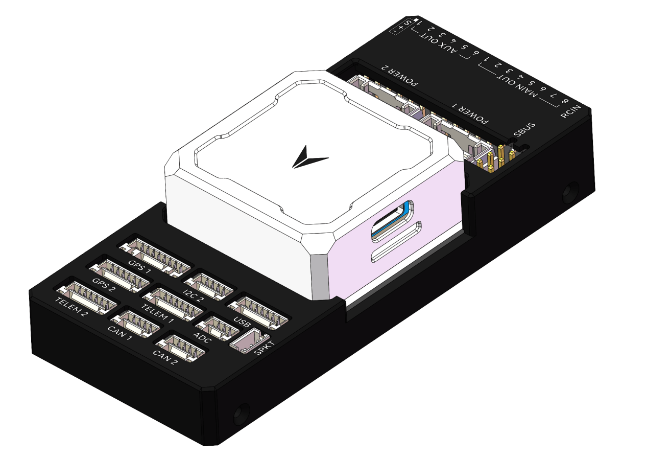
Pinout


UART Mapping
SERIAL0 -> USB
SERIAL1 -> UART2 (Telem1)
SERIAL2 -> UART3 (Telem2)
SERIAL3 -> UART4 (GPS)
SERIAL4 -> UART8 (GPS2)
SERIAL5 -> UART7 ( CONS)
The Telem1 and Telem2 ports have RTS/CTS pins, the other UARTs do not have RTS/CTS.
The CONS port was originally used as a debug console, but is now a general purpose UART (debug output is now on USB).
Connectors
Unless noted otherwise all connectors are JST GH 1.25mm pitch.
TELEM1, TELEM2 ports
GPS1 port
GPS2 port
CONS port
The CONS port is an additional UART connected to SERIAL5. The pinout in the CONS port table below is ordered so that the GND pin is closest to the flight controller. The TX pin is closest to the servo rail.
SBUS Out port
The SBUSo port is a port attached to the IO processor which can be used to output all servo channels via SBUS. It is enabled by setting the BRD_SBUS_OUT parameter.
The pinout below for the SBUSo port is labelled so that GND is closest to the flight controller. The 5V pin on the SBUS output port is connected to the servo rail.
When SBUS output is disabled (by setting BRD_SBUS_OUT to 0) you can use the port for analog RSSI input from receivers. To enable for RSSI input you need to set:
BRD_SBUS_OUT 0
RSSI_TYPE 1
RSSI_PIN 103
You cannot have both SBUS output and analog RSSI input at the same time.
SPKT port
The SPKT port provides a connector for Spektrum satellite receivers. It is needed to allow for software controlled binding of satellite receivers.
The pinout of the SPKT port given below is given with the 3.3V power pin closest to the flight controller (pin 3).
ADC
I2C2
FMU and IO SWD
When the case is removed there are two SWD connectors, one for FMU and the other for IOMCU. The IO SWD connector is the one closer to the servo rail. The GND pin of both connectors is the one furthest from the servo rail.
CAN1&2
POWER1&2
USB
RC Input
RC input is configured on the RCIN pin, at one end of the servo rail, marked RCIN in the above diagram. This pin supports all RC protocols. In addition there is a dedicated Spektrum satellite port which supports software power control, allowing for binding of Spektrum satellite receivers.
PWM Output
The flight controller supports up to 14 PWM outputs. First first 8 outputs (labelled “MAIN”) are controlled by a dedicated STM32F100 IO controller. These 8 outputs support all PWM output formats, but not DShot.
The remaining 6 outputs (labelled AUX1 to AUX6) are the “auxiliary” outputs. These are directly attached to the STM32H743 and support all PWM protocols as well as DShot.
All 14 PWM outputs have GND on the top row, 5V on the middle row and signal on the bottom row.
The 8 main PWM outputs are in 3 groups:
PWM 1 and 2 in group1
PWM 3 and 4 in group2
PWM 5, 6, 7 and 8 in group3
The 6 auxiliary PWM outputs are in 2 groups:
PWM 1, 2, 3 and 4 in group1
PWM 5 and 6 in group2
Channels within the same group need to use the same output rate. If any channel in a group uses DShot then all channels in the group need to use DShot.
Battery Monitoring
The board has two dedicated power monitor ports on 6 pin connectors. The correct battery setting parameters are dependent on the type of power brick which is connected.
IMU Heater
The IMU heater in the flight controller can be controlled with the BRD_HEAT_TARG parameter, which is in degrees C.
DroneSafer Flight Controller Series
Compare flight controllers by interfaces, sensors, and supported GPS/RC systems.